Choose the language.
TKART magazine Tech Talk | The kart master cylinder
Exclusive Content

THE KART MASTER CYLINDER

Gianluca Covini
31 May 2023 • 15 min. read
alt
It’s the "heart" of the braking system, which puts the brake fluid under pressure. In addition to describing its composition, functioning and main characteristics, we also find out what affects its stroke when braking
alt
alt
Advertisement
The master cylinder is literally the heart of the kart braking system. In fact, it is the component that puts the brake fluid under pressure, sending it to the pistons installed in the calipers (the operation of which we described in detail in the article "Technique | Everything about the brake caliper"). Structurally, the master cylinder is made up of a cylinder which houses a piston (referred to as the piston), controlled directly by a shaft, which is in turn connected to the brake pedal via a steel tie rod. The piston forms a chamber which, in the rest position, is connected, via a hole called the compensation hole, to the liquid tank which is at atmospheric pressure. A spring keeps the piston in the rest position. The configuration used in karts is a single piston with a tank, but there is also a "Tandem" configuration, with a double piston (one in a row) and a double tank.
This is the one used in cars where there is a double circuit. In karts there is only one circuit (in fact there is only one circuit that reaches the calipers), i.e. if a brake pipe that goes to the wheels is severed, the kart will no longer brake. As far as the world of karting that complies with the FIA Karting regulations is concerned, the brake master cylinders must comply with the relevant approval regulations (for further information, read "Dossier | FIA Approvals: what they are, what they are for, how long they last ... the definitive guide!"). In any case, the development of the master cylinder cannot ignore its surroundings, especially the kinematic mechanism that moves the piston according to the stroke of the brake pedal, but also other elements such as the tank, distributor and any pressure reducing valves.
Structurally, the master cylinder is made up of a cylinder which houses a piston (referred to as the piston)
alt
alt
Image 1 Main components of the master cylinder: [1] master cylinder body (with tank cover removed); [2] linkage dust cover (not always present); [3] control lever pin; [4] control lever; [5] piston with sealing gasket; [6] piston return spring. Image 2 The body of a master cylinder is generally made of aluminium (there are also models machined from a solid piece), obtained from a forged piece machined using CNC machines. Externally, the pump is then anodized, like other elements of the chassis, to improve protection from external agents. The shaft may be made of aluminium or Ergal (Al-Zn-Mg alloy). The piston is also made of aluminium, with a surface treatment (such as an anticorodal treatment) to increase its resistance to wear and corrosion, and there are also plastic models. The return spring of the piston is made of steel enriched with silicon, to improve elasticity.
The first element in the kinematic chain of the braking system is the brake pedal which, according to FIA Karting regulations, must be fastened to the main tubes of the chassis. The ergonomics of the brake pedal determine the ratio between the force applied by the driver on the pedal and that impressed on the brake master cylinder piston. The ratio is easily calculated by dividing (B) the distance from the pedal to the fulcrum of the lever by (A) the distance from the control rod (or pulling cable) to the fulcrum of the lever. As the ratio increases, the stroke on the brake pedal will increase, but the effort required by the driver to brake will decrease. Usually the pedals have several anchoring points of the control rod, in order to vary the ratio, and therefore the feeling on the pedal according to the driver's preferences.
The position of the pedal in relation to the control lever is also adjustable in some cases. It should be emphasised that part of the force generated by the driver's foot is lost in internal friction and therefore the efficiency of the pedal linkage is referred to: generally it is 0.8 and also takes into account the force that is lost to overcome the load provided by the springs in the master cylinder. The FIA Karting technical regulations require that the control between the pedal and the master cylinder be made with a steel tie rod plus a guide wire (to ensure the safety of the system) fastened with at least two clamps for each terminal. Or you can opt for a double steel wire (two distinct sheaths), the minimum diameter of which must be at least 1.8 mm.
PEDAL RATIO
alt
alt
Image 1 Brake pedal linkage diagram: R_pedal = B/A. Image 2 For many pumps there is a second reduction ratio to consider, generated by the control lever which acts on the piston. The control lever rotates around a fulcrum linked to the pump, and therefore the equation becomes F1 x r1 = F2 x r2 (as can be seen in the figure). Typically r2 is smaller than r1, so F2 (the force acting on the displacement pump) is greater than F1. The ratio is therefore R_pump = r1/r2 and is greater than 1. In other words, it is able to increase the force generated on the piston, at the expense of a small increase in stroke. In the example in the figure, the distance r1 can be adjusted through several anchor points of the control rod (or pulling cable).
PISTON DRIVE [A]
1 di 4
alt
alt
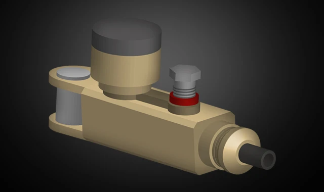
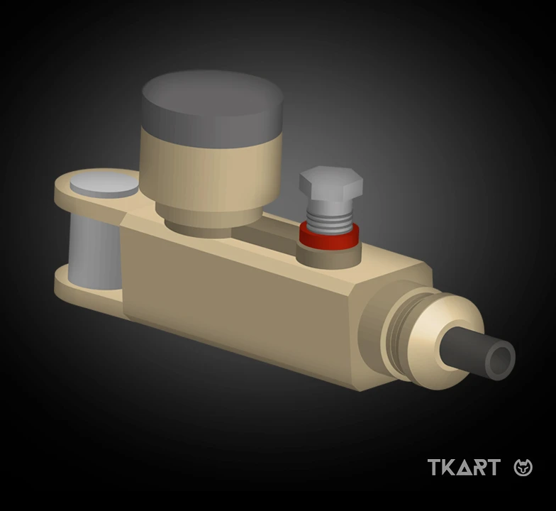
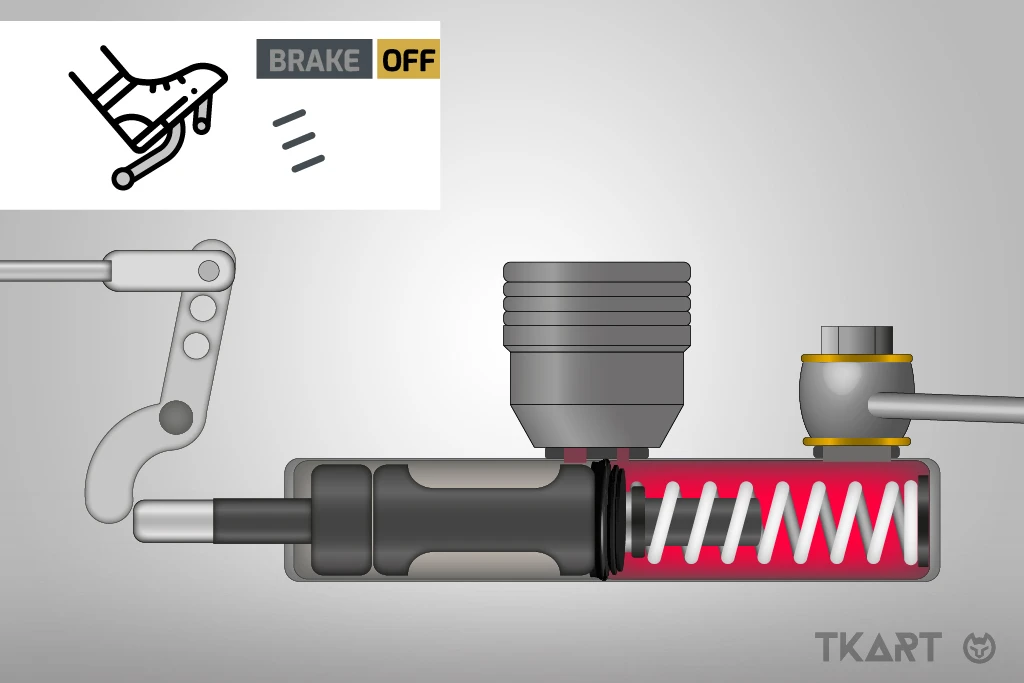
As just explained, the brake master cylinder (also called master cylinder) is controlled by the kart's brake pedal via a system of levers and tie rods. The driver imparts the braking force by pushing the pedal with a force that can reach up to 40-50 kg. At that point, the force, multiplied by the ratio to the pedal, is transferred to the piston inside the pump, which puts the brake fluid under pressure (which we have already explained in the article “Technique | brake fluid"). In most braking systems, the piston is driven by compression, i.e. the rod pushes the piston, while in some systems the rod works based on traction, pulling the piston towards the front of the pump (moreover, there are braking systems which have both types of drive, to learn more read "Technical Focus | LKF13 and LKF14, the braking systems with the "two-in-one" master cylinder by Lenzokart").
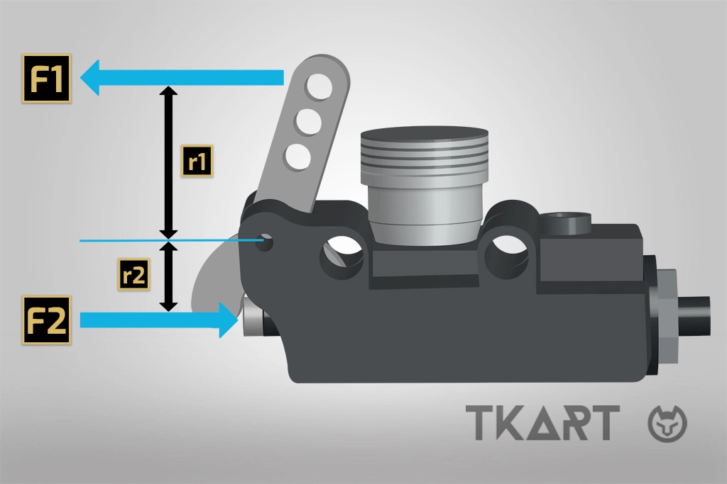
The force on the piston rod and the brake fluid pressure are related by the equation P = F / A. Where: P is the pressure of the brake fluid, F is the force exerted on the piston rod and A is the internal diameter of the pump, given that it generally varies from 13 to 22 mm (with the same boundary conditions, the greater the diameter of the master cylinder the greater the force required to brake the kart, but the smaller the stroke). The liquid then transfers the pressure to the pistons housed in the calipers, net of pressure drops in the hydraulic circuit. The friction force between the pads and the disc therefore acts on the wheels, decelerating the wheels and the kart.
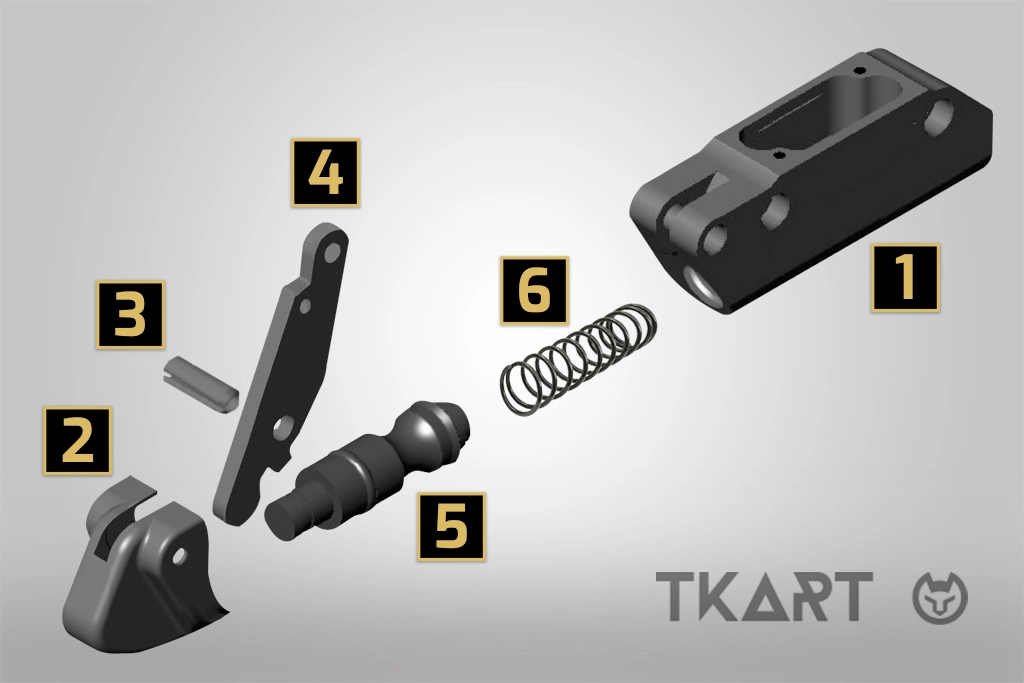
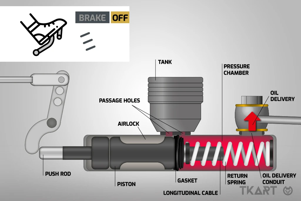
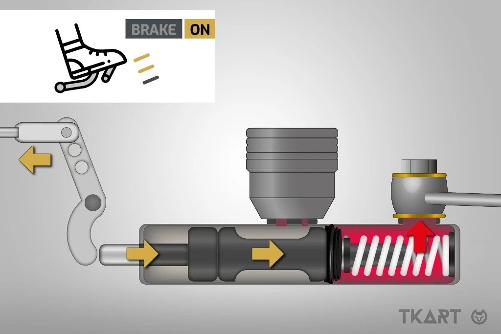
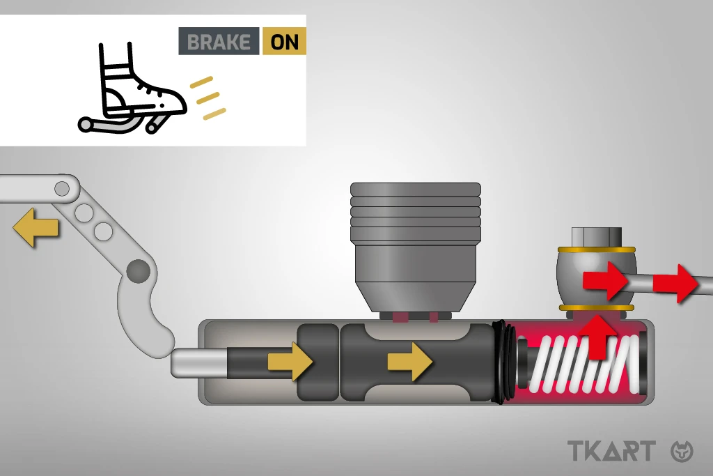
[A]
Assuming that the piston is driven by thrust, when the driver presses the brake pedal, the rod pushes the piston by means of the control lever, until this closes the hole and stops the passage of liquid from the chamber to the tank; the continuous movement of the piston then generates pressure in the chamber and therefore to the ducts directed to the brakes on the wheels. The piston has a longitudinal cable, which works radially with the gasket housing, so that the pressure of the chamber is applied to the internal diameter of the gasket, pushing it against the cylinder walls, thus increasing its seal.
Continue reading the article by subscribing for only 0.96 € / week
7
Explore these and many other
premium contents
Go to Magazine