Choose the language.
TKART magazine Doctor TKART | How to adjust the toe of the front wheels with the laser measurement kit
1
Exclusive Content

HOW TO ADJUST THE TOE OF THE FRONT WHEELS WITH THE LASER MEASUREMENT KIT

Giacomo Mantovani
18 September 2022 • 12 min. read
Step-by-step guide to check and adjust one of the characteristic geometries of the front axle (together with the caster and camber) with the most precise instrumentation available on the market today: optical measurement
alt
THE TASK IN SHORT

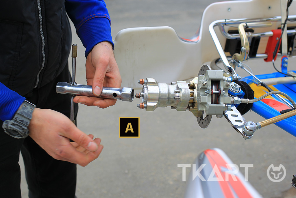
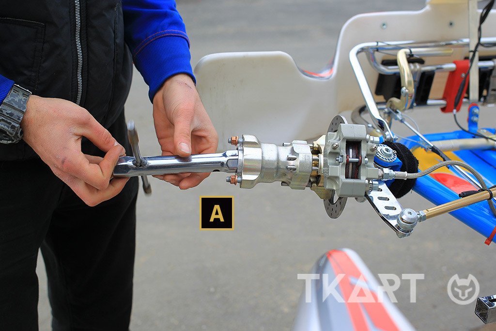
Dismantle the front hubs to install the laser pointers, check the front alignment and correct the toe as required.

time 20 min
difficulty Normal
Advertisement

The toe, that is the angle formed between the front wheels and the longitudinal axis of the kart, is a fundamental parameter to determine the behaviour of a vehicle both on straights and bends, which is why it is important to adjust it correctly to have a good feeling with the kart and maximise its performance. With the article “Tecnique - The toe”, we have explored all the theoretical details concerning this characteristic geometry of the front axle, while in a dedicated "Doctor TKART” we described how to adjust the trim with the aid of the specific discs.

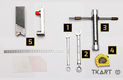
However, in this guide we show how to check and adjust the toe angle using a laser measurement kit. An instrumentation that allows, for the same time taken with respect to the same activity performed with the toe discs, also to prepare further checks in order to further refine the set-up of the kart.

N.B. The activities described below are valid for any type of kart: Mini, Junior/Senior single speed and Junior/Senior with gears.

NECESSARY TOOLS
5 KART LASER MEASUREMENT KIT [A] 2 pointers [B] semi-transparent plate [C] graduated rod
4 EXTENDABLE RULER
3 22 MM TUBE KEY
2 13 MM KEY
1 10 MM KEY
alt
1
STEP
5 MIN

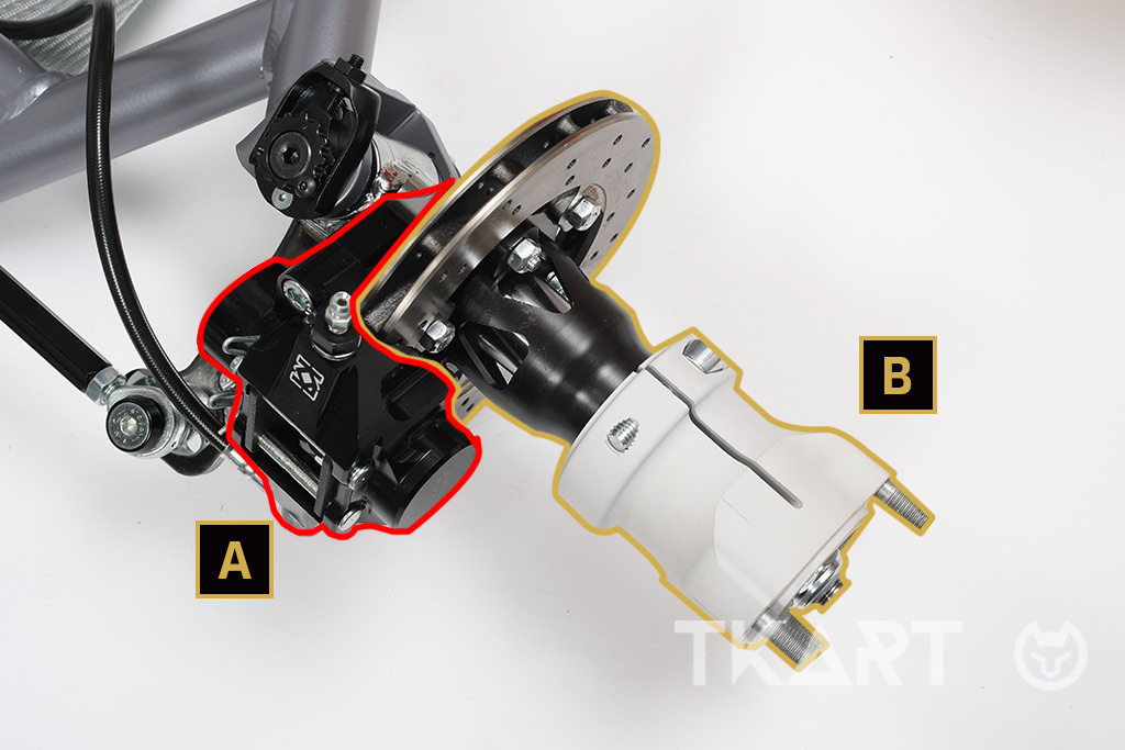
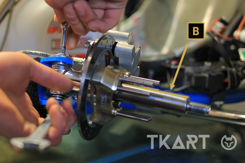
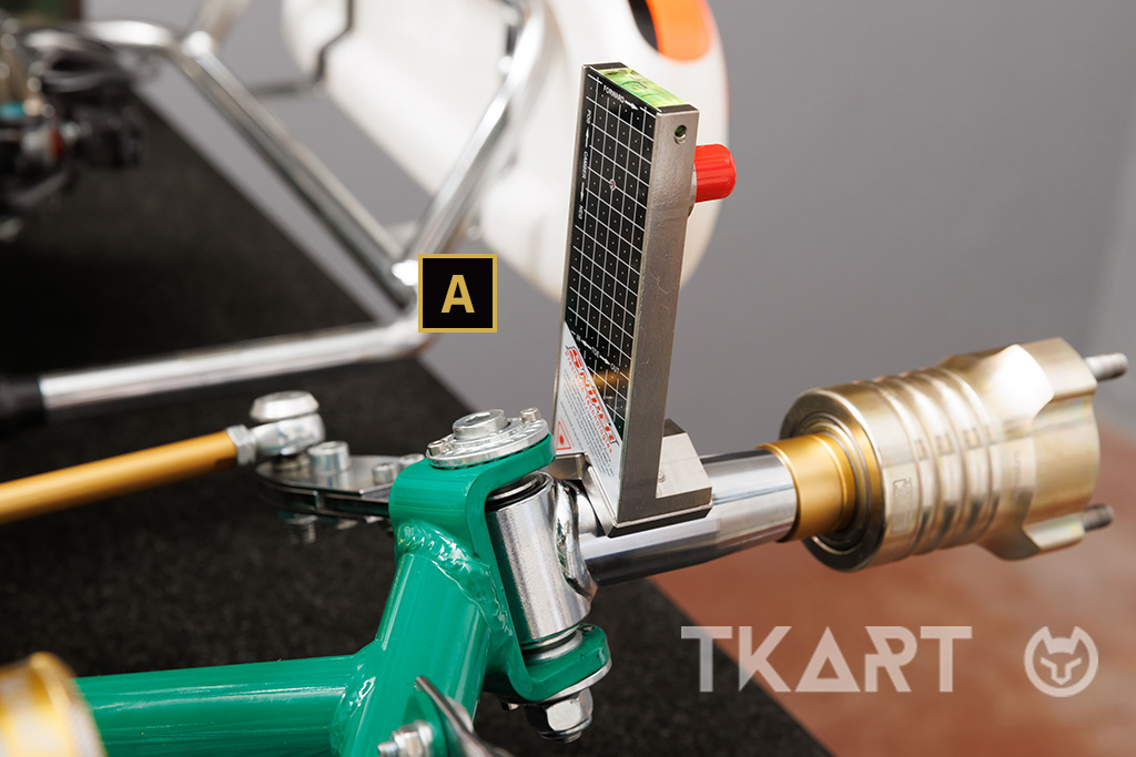
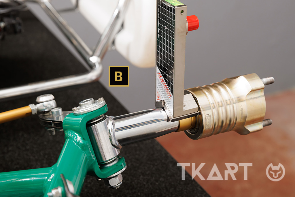
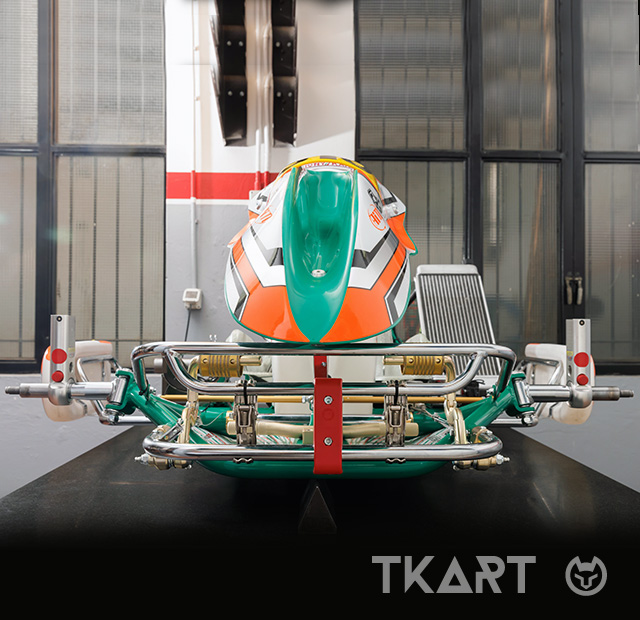
To check the toe of the front wheels it is necessary to place the laser pointers (regardless of the fastening system they have, magnet or flange) directly on the machined part of the spindle pin. To do this, first of all you have to position the vehicle on the trolley and make sure that the chassis is parallel to the ground (to be sure of this, we have placed the chassis on a surface, but it is not essential). Then all the components in this area must be removed (even as a block without dismantling them individually): wheels, hubs (and any thicknesses), disc/disc holder and brake calipers. In our case, the object of the toe adjustment will be a chassis in a direct-drive configuration, therefore without a front braking system. This allows us to speed up this phase by a couple of minutes, compared to the same activity carried out on a shifter kart, since it will only be necessary to remove the front wheels/hubs.

1. It is important to free (on both sides) the spindle pin so as to be able to use the machined part (the one on which the hubs or disc holders are generally mounted) as a fastening point for the laser pointer. To do this it is generally necessary to remove the wheel, the [A] brake caliper and the [B] “disc-disc holder-hub” assembly. If for lack of time, you cannot dismantle all the parts indicated above, you can also just dismantle the hub and attach the laser pointers in contact with the disc holder. Although this is made of non-magnetic material, the laser pointer equipped with a magnet will remain sufficiently anchored as a minimum of magnetism will be ensured by the pin of the spindle below. This method will be applicable only after activating the braking system (by pressing the pedal fully and keeping it locked in that position, with a clamp anchored to the upper front bumper) so as not to allow the rotation of the disc holder.
alt
2. In other cases, for example ours, it is possible to avoid dismantling the brake calipers and the discs/disc holders because only [A] by removing the hubs, using a 22 mm socket wrench, you get [B] the necessary support surface for positioning the magnet lasers.
alt
2. In other cases, for example ours, it is possible to avoid dismantling the brake calipers and the discs/disc holders because only [A] by removing the hubs, using a 22 mm socket wrench, you get [B] the necessary support surface for positioning the magnet lasers.
alt
2. In other cases, for example ours, it is possible to avoid dismantling the brake calipers and the discs/disc holders because only [A] by removing the hubs, using a 22 mm socket wrench, you get [B] the necessary support surface for positioning the magnet lasers.
alt
. WARNING! Although it is physically possible, installing laser pointers directly on the hubs is a practice to avoid since it could negatively affect correct toe measurement. We have selected two quite common errors: [A] the pointer is correctly fastened, but there is no certainty that the support base is parallel to the axis of rotation of the front wheels, with the consequence of assuming incorrect references that lead, in fact, to wrong measurements. [B] Despite being in a better position than the one just shown, the pointer may have a support plane that is not perfectly parallel to the rotation axis. However, a solution of this kind could be used to check the toe under load, i.e. with the driver on board and the chassis on the ground. Note that the toe measured under load will be more closed by about 1 mm per side compared to the value measured with the kart on the trolley.
alt
Continue reading the article by subscribing for only 0.96 € / week
12
Explore these and many other
premium contents
Go to Magazine